Glossary on electricity

A

AC current:

A current that alternates periodically between positive and negative values. The current provided by the electrical supply network is an AC current of sinusoidal appearance, with a period of 20 milliseconds which corresponds to a frequency of 50 Hz (in Europe). The period is defined as the time elapsed between two passages of the same value of the current.

Note: The period is the reverse of the frequency: 1/50 = 0.02 s or 20 ms

C

Conductivity:

The conductivity of a material indicates the degree of facility to which current flows through the material.

Conductivity (δ in S.m-1, siemens per meter) is the inverse of resistivity (ρ in W.m).

Contact current (Ic):

Contact current is a current that runs through the body between two points of contact (generally, a hand and a foot or between both hands / feet) with electrical conductors at different potentials (a device and the floor, a tap and the floor a heater and the floor…) while this voltage is first of all not obvious since no object is connected to a voltage source.

Contact current is a current that flows all the time during the contact, thus it is neither a transitory phenomenon, nor an impulse. This current is at power frequency (50 Hz in Europe).

For safety purposes related to electrocution risks, residential electric wiring are protected against contact currents when they exceed 30 mA (bathrooms), or even 300 mA. This measure aims to protect from ventricular fibrillation risks.

However, contact current intensity is generally weak in well-designed house wiring in good maintenance. Let’s also add that shoes partly insulate from the ground and, by the way, limit contact currents.

Very often, contact currents are not perceived (the perception threshold of human being is around 0.2 to 0.4 mA; source : ICNIRP, 2001; http://www.icnirp.de/documents/emfgdl.pdf). Exceeding perception threshold does not directly trigger the circuit-breaker. However, if a problem arises with the washing machine, for example, the differential will work if the current exceeds 30 mA to avoid any direct health hazard.

It would be mistaken to believe protecting our house wiring to levels lower than 30 mA because inopportune triggering would be too numerous.

Note:

  • Contact current is another source of current that can flow through the human body, different from the one related to ambient electromagnetic fields (called induced current).
  • Contact current neither means there is a contact with active parts (contact with live parts), nor electrostatic discharges (ESD).

Current:

Electrical current is a physical phenomenon caused by the displacement of a charge (ion or electron). In the case of a metal conductor, electrons play the main part in the current. The current’s intensity is the quantity of charge that passes in a conductor per unit of time. The current’s intensity is measured in amperes (A).

Current density:

The density of current is the intensity of the current per unit area and, is measured in amperes per square meter (A/m2).

D

DC current:

A current whose value is constant in time, e.g. the current output by a battery.

E

Electric energy:

It is the product of the power with the number of hours in operation. It is expressed in kilowatt hours (kWh) at the domestic level and in Terawatt hours (TWh) at the entire country level. The average annual consumption for a Belgian household is 4000 to 6000 kWh. Belgium consumed approximately 80 TWh in the year 2000 (more or less one-third for domestic use).

Electric field (E):

The electric field is a field vector (i.e. a collection of values and directions for all points of a given space), just like the terrestrial field of gravity. Its direction depends on the electric charges present. The value and direction of the electric field at a given space location is obtained by placing a virtual positive unit electric charge at that location: the electric field at this point is the force (expressed in newtons) acting on this virtual charge. (F=qE with q = 1 coulomb).

Any electric charge “q” (unit : coulomb) creates an electric field “E” in the space that surrounds it. The intensity of the electric field is expressed in volts per meter (V/m).

The electric field is perpendicular to an equipotential surface, e.g. the ground (assumed perfectly conducting) or an electrically conductive surface. Within a perfectly conducting object (e.g. a metal cage), the electric field is equal to zero if there are no internal sources within the object. The human body, for example, being a relatively good conductor, has an internal electric field nearly equal to zero (magnitude of mV/m), even if one plunges it into an intense external field of several kV/m say, 6 orders of magnitude stronger. An electrical current passing through an imperfect conductor also creates an electric field in the direction of the current.

A didactic explanation is proposed in the EMF header.

Electromagnetic compatibility:

According to Council Directive 89/336/EEC of 3 May 1989, electromagnetic compatibility is the capability of a device, unit of equipment or system to function satisfactorily in its electromagnetic environment without introducing intolerable electromagnetic disturbances to anything in that environment.

Electromotive force:

The electromotive force of a device corresponds to the work per unit charge needed to conduct this charge in a closed loop. It is also the potential difference (in volts) induced or imposed that supplies a circuit.

Electrostatic discharges:

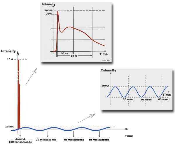
Electrostatic discharges are observed during the counterbalancing of potential between two bodies, initially at a potential difference. The almost instantaneous discharge (within a few billionth of a second) brings only momentary discomfort, related to a burning sensation that comes from the passage of an intense but short shock. This type of contact current is never the origin of real disorders, considering its short duration. It is typically the discomfort observed when touching a metallic object (door or car handles) under particular circumstances.

Here is a graph showing the difference between a leak current and an electrostatic discharge:

Electrostatic discharge intensity (red line) and leak current (blue line)
in accordance with time

ELF:

Extremely Low Frequency.

Exposure:

Exposure is the condition of being subjected to a factor. Measurement of exposure can be carried out in a direct way with a measuring apparatus. It can also be evaluated in an indirect way by a calculation method or an estimate. In the case of magnetic fields, two methods of indirect measurement are frequently used: the ” wiring code ” for studies in the general population and professional title for studies in the occupational environment.

F

Fault current:

Fault current is an abnormal usually very intense current (several thousand amps) which travels through a network when a fault occurs.

The fault may be a contact between phases, between phase and earth, between phase and neutral. The contact generally (but not always) has a low impedance. Fault currents are often called short-circuit currents (the circuit being “short” since it bypasses the load).

Short-circuit currents depend on the upstream network power and has nothing to do with the load. The current originates in the distribution network: in high voltage environments, short-circuit currents have reached 63,000 amps. In low voltage residential setups, currents of a few thousand amps are possible, depending on the distance to the local transformer.

Hazards created by short-circuits are twofold: on one hand, there can be indirect contact with people (high voltage only), and on the other, overheating of cable insulation (accelerating the aging of the wiring), eventual fire, and loss of balance among the 3 phases at the distribution level and its dangerous consequences. There can also be some mechanical effects due to the Laplace forces (attraction between conductors if the current in each is in the same direction, or repulsion in the reverse case); these forces are normally negligible in low voltage settings, but can be significant with high voltage, this is why it is a key consideration in the design of high voltage structures.

Protection against fault currents is achieved by means of fuses or circuit breakers which must quickly interrupt the circuit and limit the damages.

Note that most fault currents (such as short-circuit between phase and neutral) in a residential setting doesn’t make an RCD trip since the current remains the same in both directions.

Frequency:

The number of identical regular cycles during one second. Frequency is expressed in hertz (Hz). It is the inverse of the period, which is expressed in seconds : 1 Hz = 1/s.

I

Induced current in the human body

An induced current in the human body is a current that flows through the human body without an electrical conductor being touched.

The human body is roughly a salt water ball, quite a good electric conductor. If we plunge such a body in a variable electromagnetic field (for example with a 50Hz sinwave like power frequency), it will be travelled by a current at the same frequency than the one of the ambient field. This current makes closed loops inside the body.

In low frequency fields (ELF), the electric field E and the magnetic induction field B are separately considered.

  • Variable external electric field E (ambient) (expressed in kV/m) will be highly perturbed by the presence of this electrical conductor, surface charges will appear at the surface to attempt to cancel the electric field inside the body, without, however, totally succeeding in doing this seeing that the body is not a perfect conductor (electrical conductivity of internal part of the body varies according to tissues).
    It is considered that an electric field inside the body can be reduced from a one million factor (in comparison with an external ambient field), thus only some mV/m remain inside the body for some external kV/m. Induced current inside the body is related to an internal electric field by Ohm’s law (that connect current density, electric field and tissue conductivity).
  • Variable external magnetic induction field B (expressed in microTesla) is slightly disrupted by the presence of an electrical conductor. The reaction inside the conductor is made as the appearance of a loop of current that will attempt to cancel the applied external field. Again, this induced current is related to internal electric field by Ohm’s law.

Induced current by an electric field and a magnetic field can overlap but it is quite complex seeing that the direction of these induced currents (parallel to internal electric field) are not the same depending on whether they are induced by E or B because of subtractive or additional effects.

Intensity - Potential difference

One can compare intensity to the current of a river. The flow (i.e. water quantity per unit of time) would be analogous to the intensity expressed in amperes (A). The pressure would be the potential difference expressed in volts (V). As there can exist pressure (e.g. through a difference in level) without a corresponding water circulation, one can detect electricity without a corresponding circulation of electrons. Thus the terminal voltage of a plug is present if a light is switched on or off. On the other hand, one can not detect intensity if the appliance is switched off.

L

Leak current

Earth leakage is first of all a current …leaking to earth! It is not a fault current (which leads to an overload and trips a protective device), neither is it a contact current (which goes through the body, depends on the impedance (*) of the person creating the contact and on whether the appliance is earthed or not), nor is it an electrostatic discharge (see the graph showing the difference between an earth leakage and an electrostatic discharge). It is generally limited to a few microamperes, possibly milliamperes.

(*) The electric impedance is a measure of the opposition to a sinusoidal alternating current in an electric circuit. Its symbol is Z and it is measured in ohms.

It is a weak current that leaks from the network and flows out of the electrical installation, assuming no actual “fault”. It is not incompatible with the apparently normal operation of electrical devices. It sometimes increases over time because of the progressive deterioration of the insulation. (see “In more technical detail”).

The leakage exists because a connection through a very high impedance, though not infinite, exists between the live conductors in a circuit and the other conducting parts of the appliance (metallic frame, etc.). For a current to exist, the circuit must be somehow closed, this can happen in several ways:

  • If this “connection” impedance is very high, say more than a few tens of MΩ (megohms) in our 230 V residential installation, the earth current will be very small. For example, for an impedance of 2.3 MΩ between live conductors and the other conducting parts, the current will be 100 microamperes of leakage.
  • When the impedance is not quite as high, the conducting parts of the appliance (such as the metallic frame) are at a non negligible potential. The earth current may become sizeable, say a few mA. In order to avoid this problem, building regulations require that appliances be earthed (metallic frames, enclosures, etc.). That way, the frame is practically at earth potential, since the earth conductor impedance is typically only between 10 to 20 ohms. If the impedance of the insulation fault is still high (otherwise, you’d get a short circuit), the earth current will just drain through the earth conductor. The exact potential of the appliance frame can be calculated as the earth current, say 10 mA multiplied by the impedance of the earth conductor, say 10 Ω, is a potential of 100 mV. Note that in order to have a 10 mA earth current, the impedance due to the insulation deterioration would have to be 23 kΩ. This is very rare in a correctly isolated installation, but it can also happen because of the presence of anti-interference filters (capacitors between live conductors and the frame).Without earthing, the frame would be at a potential different from that of earth, waiting for the unhappy soul who will make the connection with earth. This would be dangerous as earthing will take place through that person who will be electrocuted by the current (contact current this time).

Note: An earth leakage of 10 mA for example doesn’t mean that the contact current would be 10 mA because in that case, the current will depend on the additional impedance of the body, the contact points (hand-frame or feet-floor), and of the return circuit through the ground.

Earth leakage currents have the same frequency as the underlying current. Thus we can assume that it is alternating at 50 Hz (in Europe), that is with a 20 ms period, except that harmonics are almost always present (predominantly 5, 7, and 11 times 50 Hz) but with much lower amplitudes.

As we just saw, earth leakage currents present a danger for people safety.

An RCD does protect against earth leakage as it will trip whenever the difference between phase and neutral exceeds a predetermined value. Typically, the limit is 300 mA for complete installations and 30 mA in bathrooms (note that only 30 mA RCDs protect people; 300 mA protects mostly against thermal overloads and the risk of fire).

Earth leakage currents present practically no risk of fire.
Fuses and circuit breakers do not react to leakage current.

In more technical detail …

Earth leakage current path impedance has two components: resistive and capacitive:

  • The capacitive component exists continuously as it is due to the fact that some of the alternating current escapes the wires, even in perfect condition, by capacitive effect; but it leads to only a few tens microamperes for a complete residential installation.
  • The resistive component is due to the partial degradation of the wires insulation (when the degradation is total, it creates a short-circuit and a fault current). The partial degradation reduces the impedance to a non-infinite value between the wire itself and the outside. This is where the current “leak” out of the network occurs.

This leakage current must be both channelled and limited in amplitude. Channelled to prevent metallic parts of a device from acquiring a potential; earthing takes care of that. Limited for two reasons: (i) in case where metallic parts acquire a potential other than earth (earth fault), its amplitude is harmless and (ii) avoid having a resulting current capable of electrocuting someone.

M

Magnetic field (H)

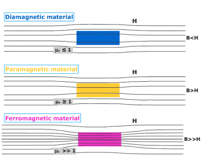
The magnetic field H (which is expressed in A/m) is related to the magnetic induction field B (expressed in teslas or T) by a physical size characteristic of the medium in which the field exists. This physical size is called the magnetic permeability of the medium. It is expressed in henry per meter (H/m) and is often represented by the letter µ. In the majority of materials (e.g. air, vacuum, gas, copper, ground), this size is a constant with a value of 1.25666 10-6 H/m. It differs from this value in materials known as ferromagnetic (used for magnets, sheets of transformers), in which case this value can be several tens of thousands of times greater. B=µH

The lines of field and induction field can thus be very different in the presence of ferromagnetic materials.

Magnetic flux density

Magnetic flux density is another term for the ” magnetic induction field “.

Magnetic induction field (B)

One readily speaks in the literature of magnetic field instead of the adequate expression “magnetic induction field “. Electric charges at rest generate an electric field. Moving charges (i.e. electrical current) create a magnetic field, known as a magnetic induction field.

B-field is expressed in Tesla (T) in International Unit. Often, to avoid too much zeo, it is expressed in mT (milliTesla) or µT (microTesla). In the literature, we can also see Gauss (G). Conversion is as follows: 1 Tesla= 10.000 Gauss or 1 µT = 10 mG.

Magnetic permeability of a material

The magnetic permeability of a material is the capability of this material to channel magnetic induction, in other words, to concentrate magnetic flux lines and thus to increase the value of magnetic induction. It means that this value depends on the material in which it is produced.

The chanelling of the magnetic field in a material which is also a conductor is especially reduced, because of induced current when frequency of field variation, permeability and conductivity are high.

In fact, magnetic field H and magnetic induction field B are linked, in a given material, by the equation :

B = µ * H

where µ is the magnetic permeability of the material (in Henry/meter).

The magnetic permeability of a material (µ) is expressed by the product of vacuum permeability (µ0, in Henry/meter) and relative permeability (µr, without dimension) :

µ=µ0 * µr

  • µ0 is a universal constant, equal to 4 π *10 -7 H/m
  • µr depends on the material.

In air, a vacuum, gas, copper, aluminium, earth and other materials, µr is equal to 1. These materials do not lead to a chanelling of the magnetic field.

Different kind of materials

We can distinguish diamagnetic (Silver, Copper, Water, Gold, Lead, Zinc …), paramagnetic (Air, Aluminium, Magnesium, Platinum…) and ferromagnetic (Cobalt, Iron, Mumetal, Nickel …) materials.

In general, diamagnetic and paramagnetic materials present permeability values close to 1. Thus, the absolute permeability µ of diamagnetic and paramagnetic materials is practically equal to the one of the vacuum, i.e. 4 π *10-7 H/m.

The permeability of ferromagnetic materials is not constant but depends on the magnetic field H. For low values of H, µr can be very high, but it decreases with H value and can become equal to 1 above a certain threshold, because of a saturation. For this reason, we indicate maximal values of relative permeability in the table below.

Table – Relative magnetic permeability of ferromagnetic materiels at 20°C

Ferromagnetic material Relative magnetic permeability (µr)
(max value)
Cobalt
Iron
Mumetal
Nickel
250
10 000
100 000
600

Influence of temperature

A particular temperature exists, called Curie temperature (Tc) or Curie point, above which ferromagnetic materials lose their ferromagnetic property :

  • Cobalt : 1115°C
  • Iron : 770°C
  • Mumetal : 380 °C
  • Nickel : 358°C

Above the Curie temperature Tc, ferromagnetic materials become paramagnetic.

Further information in http://en.wikipedia.org/wiki/Curie_temperature

Origins of magnetic properties of materials

To understand differences in relative permeability, it is necessary to start from characteristics of atoms constituting materials. Either solids, liquids or gas, materials are constituted of molecules, which are made up of atoms.

An atom contains a central nucleus with orbiting electrons. Electrons move around the nucleus. Moreover, we can say figuratively that they also turn around themselves. This is this rotation of electrons or SPIN that gives magnetic properties to materials.

For further information on this subject, we advise you to follow the links below :

O

Ohm's law

Ohm’s law explains the relationship between voltage and current that it produces.

To understand the relationship, let’s take the example of water spurted out from a high pressure washer. The hosepipe section is very small. When the washer is turned off, the rate of water flow is weaker at the output of the hosepipe than directly at the tap. This decrease arises from the resistance of the hosepipe to water flow.

When the washer is turned on, pressure is enhanced at the input of the hosepipe and by the way the rate of water flow is increased through it.

In electricity, voltage V plays the role of pressure and the current i is equivalent to the rate of the flow. In the same way that hosepipe gives a certain resistance to water flow, each material gives a certain resistance R to charged particles moving which constituted it and these notions are linked to Ohm’s law:

V = R x i

… so that, as in the example above, every enhancement of resistance causes under constant pressure a reduction of current and every enhancement of voltage causes an increase of current.

P

Potential difference

Power

The energy generated or consumed per unit time. The unit of power is a watt (W). Electric power is calculated by multiplying the current intensity by the potential difference.

Power frequency

In Europe, electricity is transported and distributed with a frequency of 50 cycles per second (50 Hz). In North America, the electricity distribution network functions at 60 Hz. The frequency of 50 Hz (or 60 Hz) is called the ” power frequency “.

Power of the power stations

Power stations generate significant power (expressed in millions of watts: MW). In Belgium, the net generating capacity is around 20 100 MW (value 2014). This power is delivered on consumers’ demand. In 2014, the maximum demand took place on December 3 and was measured at 13 110 MW at 6:00 PM. The minimum demand took place on July 27 and was measured at 6623 MW at 7:00 AM. These extreme values show how electric consumption can fluctuate in Belgium.

The annual overall consumption for Belgium was 88.6 TWh in 2010, 84.9 TWh in 2012 and 83.7 TWh in 2014.

Net generation (~ gross generation less losses) for Belgium (in TWh):

Total Nuclear power Fossil fuels Renewable Hydraulic
2010 89.8 45.7 35.8 6.6 1.7
2012 76.6 38.5 28.8 7.7 1.7
2014 67.7 32.1 22.4 11.8 1.4

Belgian Import/Export (in TWh):

Import Export
2010 12.3 11.9
2012 16.8 6.9
2014 21.7 4.2

See further information and data of other countries in ENTSO-E website.

Prefixes of units

Pico p 10-12 (thousandth of billionth)
Nano n 10-9 (billionth)
Micro µ 10-6 (millionth)
Milli m 10-3 (thousandth)
Kilo k 103 (thousand)
Mega M 106 (one million)
Giga G 109 (one billion)
Tera T 1012 (thousand billion)

See also Electric and Magnetic fields pages.

Pulsated (wave)

See Wave forms.

R

Residential exposure

The exposure to risk factors in and around a place of residence.

RGIE

General Regulation of Electrical Installations

The RGIE includes certain lines of transport and electrical energy distribution. This regulation was made compulsory by the royal orders of March 10, 1981 (Belgian Monitor, April 23, 1981) and September 2, 1981 (Belgian Monitor, September 30, 1981).

See the website of the FPS Economy, SMEs, independent Professions and Energy :
http://economie.fgov.be/ (in French or in Dutch)
(Energie – Electricité – Contrôle des installations électriques)
(Energie – Elektriciteit – Controle van de elektrische installaties)

RGPT

General Regulation of Worker Protection.

The RGPT is a subdivision of social legislation governing relations between employers and workers. Social, medical and technical inspectors are qualified to note infractions, and thus have the right to inspect all companies and documents. A collection of regulations, taken mainly pursuant to the law on security (1952) and the law on the well being of workers (1996), the RGPT took form after the Second World War by the Regent’s Orders of February 11, 1946 and September 27, 1947. In order to respect the European regulation and because it became illegible, the RGPT was revised in 1993 and is being progressively integrated into the Code on Well being.

Sources:
http://www.employment.belgium.be/
http://www.emploi.belgique.be (pdf in French)
http://www.werk.belgie.be/detailA_Z.aspx?id=1008 (pdf in Dutch)

Root mean square value (RMS)

A representative value of a quantity that varies in time (e.g. an AC current, an alternating voltage, an electric field, or a magnetic field). As these values vary continuously, it is necessary to establish a typical value. Physicists created the RMS, which is an image of continuous size that is equivalent to the true non-continuous quantity in terms of energy. The effective value of a quantity oscillating in a sinusoidal way is equivalent to its peak value divided by the square root of 2 (approx. 1.41).

S

Sinusoidal (wave)

Static magnetic field

The expression ” static magnetic field ” is equivalent to ” continuous magnetic field “.

T

Three-phase current

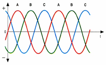
A configuration of three conducting wires wherein each one functions with the same alternating voltage, and generally transports the same AC current, but were the three currents are phase-shifted by a third of a period compared to each other. This means that the sum of the three currents is zero at every moment. A three-phase configuration makes it possible to transmit the same energy as with three identical circuits of a single wire each (compared to the same circuits with two wires each), thereby saving in 50 % in materials.

The three waves (A,B,C) represent the voltages (and currents) in a three-phase system.
Source : CIGRE

W

Waves forms

Sinusoid: an oscillating curve resembling the sine function.

Pulsated wave: a curve that does not oscillate in a sinusoidal way. Rather, it provides impulses of short durations, similar in form to a saw’s teeth.

Other topics that might interest you ...

  • Electrical concepts – Electrical concepts interesting to have in mind in order to tackle the subject of electromagnetism and electric and magnetic fields without apprehension.
  • Electric and magnetic fields – The electric and magnetic fields are distinct concepts that were developed to explain the effects of electricity at a distance. (…)
  • Electromagnetism – Electromagnetism is the study of charge interactions at a distance, of currents and electric and magnetic fields. (…)
  • Uses of EM properties – How do common domestic electrical appliances work? Based on various examples, we should gain an overall understanding of the operating principle behind those machines that convert electrical energy into thermal or mechanical energy or otherwise make use of electrostatic and electromagnetic properties.
  • Electricity network – How does the electrical grid work? All you would like to know about the transmission of electricity from power plant to the outlet on our walls.
Share