How to weaken electric and magnetic fields at home?

This question has been asked to us by a number of people. Worries can be related to the presence of a transformer, high voltage 50 Hz powerlines or cables, an inverter of photovoltaic solar cells or, less frequently, to the use of an electrical apparatus… All these devices and equipments have in common that they generate 50 Hz electric and magnetic fields.

This page will focus on 50 Hz magnetic fields, as electric fields being easily weakened by obstacles (tress, walls of homes…). Let’s see how it is possible to weaken our everyday exposure, based on the characteristics of 50 Hz magnetic fields.

In brief:

  • A cable where no current is flowing does not generate a magnetic field.
  • Keeping away from electrical devices (a few tens of centimetres) and high voltage powerline (a few tens of metres) is already sufficient to significantly reduce exposure.
  • The arrangement of cables can reduce exposure.
  • Technical solutions to limit fields are available. However, they require a rigorous implementation and are not necessarily effective. Moreover, materials are typically very expensive or require a costly implementation.

Measurements are often useful to quantify fields.

Characteristics of 50 Hz magnetic fields

1. Magnetic field intensity is proportional to current intensity

Magnetic field intensity measured in the vicinity of an electric device depends among other things on the intensity of the flowing current (or the electric power which is proportional to current). The same is true in the surroundings of electric panels, transformers, high voltage powerlines…

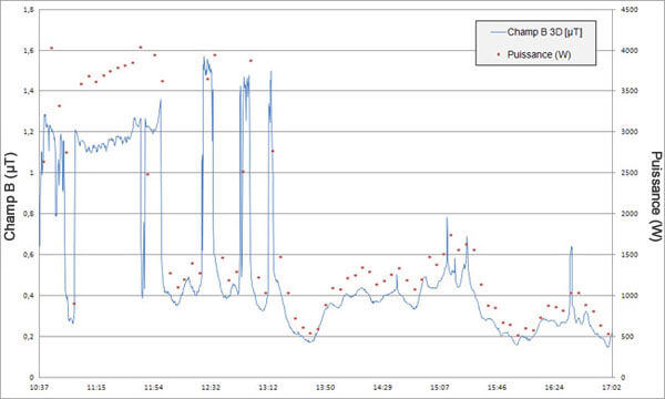
The graph below shows the relationship between the generated power (red dots on the graph) and the intensity of the magnetic field (blue curve) near an inverter of photovoltaic solar cells (Figure 1). Variations of magnetic field intensity between 10:37 AM and 5:02 PM can be seen (probe at 50 cm of the inverter). Given that panels are directed to the East, the highest values are measured in the morning. Fluctuations are related to the decrease of electricity production (see red dots) when the sun is obscured by the cloud cover.

Panneaux photovoltaïques - Puissance versus champ magnétique

Figure 1 – Variations of magnetic field intensities
(B-field in µT, recording every 16 s.)
and power delivered (in W, recording every 5 min.)
according to time

First characteristic into practice:
A cable where no current is flowing does not generate magnetic field.

2. Magnetic field intensity decreases with distance

A common characteristic of field is the decrease of intensity when keeping away from the source.

For example measurements have been made near clock-radios: when the probe was against the clock, measured values were between 15 and 25 µT according to the model. Beyond 30 cm, we were already under 0.4 µT.

For high voltage powerlines, researchers have established that at 9 m of a 70 kV line, when the load is weak, and at 36 m when the load is max, values are under 0.4 µT. In practice, the energy transmitted through the network varies during the day. On average, at 15 m of a 70 kV line, values are under 0.4 µT (see further in the page entitled Health risk issues (see Exposure analysis).

Second characteristic into practice:
Keeping away from electrical devices (a few tens of centimetres) and high voltage powerline (a few tens of metres) is already sufficient to significantly reduce exposure.

Note: How to explain important differences between the intensity of magnetic fields measured close to clock-radios?

The power of the clock, as seen in the first characteristic, plays an important role in the magnetic field intensity measured nearby. However, at equivalent powers, how can we explain the differences of field intensities? Several variables can intervene, as for example the internal construction of the clocks. Indeed, in some clocks the transformer is located in the devices while in others it is located at the electrical outlet. The current flowing in the transformer generates high 50 Hz magnetic fields. Normally these magnetic fields are confined in the transformer (it is the case of large transformers located in high voltage stations and distribution cabins) through magnetic sheets which constitute the core; however, small domestic transformers are optimized to be light and then there are significant field leakages.

The positioning of the cables and internal components, coils … also play a role in the measured values. This is the next point to be covered.

3. Magnetic field is a vector quantity

It’s a bit technical here but we will understand how the positioning of cables in appliances / devices can play a role in reducing the measured fields and how this feature can be used to reduce exposure.

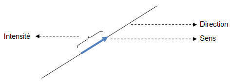
« Vector » means that the field has direction, intensity and sense. Schematically we have:

Les champs sont vectoriels

Let’s consider two particular cases:

a. Fields are of the same intensity and almost the same direction, but in opposite sense

Champs de sens opposé

The resulting field is almost nil

b. Fields are of the same intensity, almost the same direction, and the same sense

Champs de même sens

The resulting field is almost doubled

Figure 2 – Magnetic field intensity based on its sense

The positioning of the cables is important to reduce exposure.

For magnetic fields generated by overhead lines or underground cables, particular attention is now paid to the disposition of the conductors (distance minimized, positioning relative to each other …) to reduce field intensities. But it is not technically possible to reach null values; this is especially the case for cables of a high voltage transformer: the three conductors (known in the jargon as “phase conductors”) move away from each other to end at the terminals of the transformer. Distance between cables has the effect of substantially increasing the level of the magnetic fields near the transformer. As indicated above, the transformer itself is not responsible for these fields but rather the cables that supply it.

Third characteristic into practice:

Based on this characteristic, it is clear that a judicious positioning of internal cables and components can reduce magnetic field intensities. Another solution consists in compensating the field by creating an opposite field (see Absorbing shielding below).

Note: These solutions impose technical adjustments. They could be taken for example in occupational situations where workers are particularly exposed. Their implementation requires a preliminary study and a particularly careful realization.

And shielding?

A first remark is necessary: low frequency magnetic fields are not easily shielded. No solution will create an impenetrable barrier.

Let’s see how to weaken 50 Hz magnetic field.

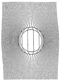
a. Absorbing shielding or shielding by Eddy currents (low-permeability high- conductivity material)a

Shielding by Eddy currents

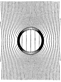
b. Magnetostatic shielding (low-conductivity high-permeability material)

Magnetostatic shielding

Figure 3 – Attenuation of the magnetic field depending on the type of shielding

Absorbing shielding uses the principles set by the laws of Faraday and Lenz (see further in the page entitled Electromagnetism):  when a conductive material is placed in a variable magnetic field an electric field is generated which in turn generates circular induced currents, called “eddy currents”. These induced currents generate a magnetic field which is opposite to the magnetic flux changes that gave rise to them.

This type of shielding requires the use of conductive materials such as aluminum or copper, of adequate thickness.

Because of the distribution of the currents induced in the material, this shielding is more effective to reduce perpendicular fields.

Magnetostatic shielding uses magnetic properties of ferromagnetic materials.

A ferromagnetic material is a material that has the ability to magnetize itself when placed in a magnetic field. This is the magnetic permeability of the material. High magnetic permeability materials (especially permalloy better known under the trade name Mumetal or grain oriented silicon steel used to make transformer sheets) are potential candidates for this type of shielding.

The field is channelled inside the material. This type of shielding is more effective in the presence of a tangential field.

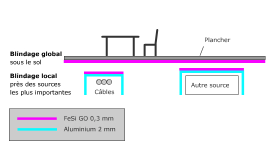
In general, especially with regard to magnetostatic shielding, to be effective, it is often necessary to use a closed shield that completely surrounds either the field source, or the area to be protected. The quality of contacts between the different parts of the shield is also essential and it will sometimes be useful to combine absorbing and magnetostatic shielding techniques of shielding (Figure 4).

Blindage local et global

Figure 4 – Picture of shielding combining absorbing and magnetostatic properties to reduce magnetic fields associated with a source placed in the basement of a house

Technical solutions to limit fields are available. However, they require a rigorous implementation and are not necessarily effective. Studies on dedicated materials commercially available have shown that even if 50 Hz magnetic field was somewhat reduced, 50 Hz electric field, meanwhile, was sometimes reinforced (Leitgeb & Cech, 2007). Furthermore, materials are typically very expensive or require a costly implementation (welding of aluminium by special techniques.

In conclusion…

These measures are preventive since, in most everyday situations, field values are low. During a measurement campaign conducted by our research group between 2001 and 2009, researchers showed that over 95% of the children tested were exposed to values below 0.4 µT.

A measurement is often useful to quantify the magnetic field. In doubt, the most effective solution is to move away the source or keep away from the source.

References

Leitgeb N, Cech R. Electromagnetic shielding mats: facts and fiction. Radiat Prot Dosimetry. 2007;123(4):450-6. Epub 2006 Dec 6.

Leitgeb N1, Cech R. (2005). Unwirksamkeit von Elektrosmog- Abschirmmatten. Teil 1: Niederfrequenzbereich [Inefficiency of electrical pollution-shielding mats. 1: low frequency range]. Biomed Tech (Berl). 2005 Jun;50(6):181-7.

Topics that might interest you ...

  • Electrical concepts – Electrical concepts interesting to have in mind in order to tackle the subject of electromagnetism and electric and magnetic fields without apprehension.
  • Electric and magnetic fields – The electric and magnetic fields are distinct concepts that were developed to explain the effects of electricity at a distance. (…)
  • Electromagnetism – Electromagnetism is the study of charge interactions at a distance, of currents and electric and magnetic fields. (…)
  • Uses of EM properties – How do common domestic electrical appliances work? Based on various examples, we should gain an overall understanding of the operating principle behind those machines that convert electrical energy into thermal or mechanical energy or otherwise make use of electrostatic and electromagnetic properties.
  • Electricity network – How does the electrical grid work? All you would like to know about the transmission of electricity from power plant to the outlet on our walls.
Share