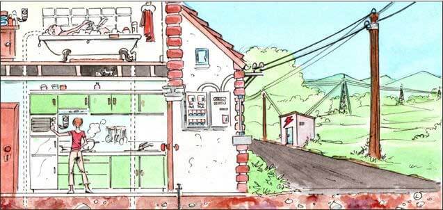
In this module, we will concern ourselves with the transmission of electricity from power plant all the way to the outlet on our walls. We will first review the features of the transmission and distribution network, and then the major elements entering into a residential electrical installation, including single phase wiring and protection methods (earthing, circuit breakers, fuses, RCD…).
Power network
High voltage transmission
Residential installations are supplied with low voltage (230 V). However, the transmission grid consists of very high voltage lines, between 380 and 150 kV in Belgium (*).
(*) Voltages from utility power stations
Utility power plant alternators convert mechanical energy supplied by water (hydroelectric plants), wind (wind farms), steam (thermal power plants or CCGT), and nuclear fission (nuclear power plants) into electrical energy.
In Belgium, these alternators generate voltages in the 10 to 20 kV range.
Very high voltages are obtained by means of step-up transformers.
Why?
The power losses due to the joule effect (mostly) are smaller in high voltage transmission lines.
Let’s look at an example:
As consumers of electrical energy, we are only interested in the amount of power which supplies our electrical equipment (example of real time power curves: Elia grid load in Belgium). In order to maximise the efficiency of the power transmission grid, the power network management must strive to limit the losses as much as possible.
The lines losses depend mostly on two parameters: the resistance of the transmission cables and the current.
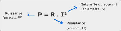
In order to minimise the losses, the current must be decreased and the transmission cable material resistance must be reduced.
We already know that the power is the product of voltage and current. A higher voltage will yield the same power with a lower current.

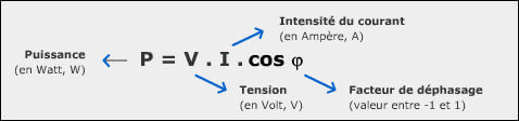
We also recall from the module ‘Basic electricity’ that the power calculation for alternating current is slightly different: the phase angle, also known as the power factor, must be taken into account, since, depending on the connected equipment (for example a motor), voltage and current are not necessarily at their maximum simultaneously. The formula thus becomes:
The resistance can be reduced by optimising the physical and electrical characteristics of the material used for the cables and by increasing their cross section.
High voltage power transmission line cables are not protected by insulation material and are usually made of aluminium.
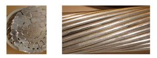
Even though its resistivity is twice as high as that of copper, aluminium has the advantage of being lighter and cheaper. However, it is not very tough, it must often be alloyed (Mg, Si…). The cables are also sometimes reinforced by a steel core.
In searching for the optimal resistance, the network designer can also optimise the conductors’ cross section. The latter is usually in the range of 150 mm² in 150 kV – 400 mm² in 200 kV – 2 x 600 mm² in 400 kV (“2 x” means that two conductors are run side by side, separated by 40 cm).
Larger cross sections are not always advantageous because of the “skin effect” (see “Alternating current transmission”). Thus it is preferable to install several 500 mm² cables per phase than to increase the cross section. Moreover, thinner cables present the advantage of being less prone to corona discharges (see “Concept of fields”).
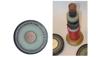
Underground high voltage cables are made of aluminium or copper and are insulated from the ground by cross-linked polyethylene (PEX) insulation.
The high (and medium) voltage power grid in Belgium consists of more than 8000 kilometres of lines, 5561 km of which are overhead lines and 2809 km which are underground cables.
| Overhead lines | Underground lines | |
|---|---|---|
| 380 kV | 891 km | / |
| 220 kV | 297 km | 5 km |
| 150 kV | 1997 km | 465 km |
| 70 kV | 2346 km | 283 km |
| 36 kV | 8 km | 1932 km |
| 30 kV | 22 km | 124 km |
(Source: Elia, 2014)
In some countries, there are some lines at 725 kV (Canada), or even higher such as China (1100 kV), Japan (planned 1100 kV), India (planned 1200 kV), and Russia where transmission tests were carried out at 1500 kV.
Note:
The higher the voltage, the higher the risk of arcing.
Because an electric arc may damage equipment and lead to current interruption, high voltage transmission requires that conductors be isolated from each other and from the tower:
- Isolation betweens conductors is obtained by the configuration of the towers;
- Isolation between conductors and the tower is done by insulators (see appendix).
Alternating current transmission
When electricity established itself as a viable form of energy, the need to carry it from producer to consumer arose. 19th century industrialists had to choose between direct and alternating current transmission. This choice was a very controversial subject with well entrenched camps battling it out. The supporters of alternating current won, even though the high voltage solution is applicable to both.
Indeed, it was quickly understood that the voltage had to be increased in order to efficiently transport electricity over long distances, but it also had to be decreased to make it usable at the user level. At that time, it was neither economically nor technically feasible with direct current, as transformers work only with alternating current.
Alternating high voltages are not however without practical problems:
- The existence of reactive power (see the paragraph on motors under “Uses of electricity”);
- The concentration of the current at the surface of cables due to the skin effect, thereby increasing their resistance and hence the losses by joule effect (*).
(*) The skin effect is an electromagnetic phenomenon which is aggravated by higher frequencies.
The result is a reduction of the “useful” cross section for the current, and consequently an increase of the conductor’s resistance.
The cross section of a high voltage overhead power line is in the order of 500 mm². But because of the skin effect, it is not advantageous to increase the size of conductors. Two 500 mm² conductors in parallel will lose less power by joule effect than a single cable of 1000 mm² cross section.
High voltage direct current is not burdened by these phenomena.
Presently, technology advancements are such that it is relatively easy to convert AC to DC and vice versa:
- Rectifiers are available to convert AC produced by a power plant to DC that can be used for transmission purposes. This avoids the capacitive and inductive complications (reactive power).
- Inverters in turn can convert DC to AC just before it reaches the final users.
In fact, high voltage direct current is in use today for very long distance transmission, for undersea cables, and to interconnect networks at different frequencies (in Japan for example where 50 and 60 Hz coexist), and a few other applications.
A bit of history
At the dawn of the electric era, the end of the 19th century, production networks were isolated from each other; every one of them had more or less arbitrarily chosen a frequency on the basis of the available production machines. There were many different frequencies.
Once electrical appliances became popular, some standardisation was necessary so that they could work regardless of the network they connected to. The standardisation of frequencies also permitted the interconnection of different power networks.
The choice of 50 Hz (in Europe, 60 Hz in the USA(*)) was the result of a compromise between the cost and size of the production machines on one hand and of the consumer’s requirements on the other. For example, too low a frequency could lead to blinking incandescent light bulbs.
(*) The 10 Hz difference between Europe and the USA is due to the choice made independently by the protagonists at the time: “though several theories and legends exist, there are some certitudes regarding the history of the 60 Hz vs. 50 Hz. […] Shortly before 1892, Westinghouse in the US chose 60 Hz, while AEG in Germany opted for 50 Hz in 1899, effectively splitting the majority of the world in two halves”.
(Source: Wikipédia – French version – August 2008)
The frequency is determined by the speed of rotation of the alternators: they produce a sinusoidal voltage alternating at 50 Hz.
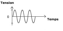
The frequency is determined by the speed of rotation of the alternators: they produce a sinusoidal voltage alternating at 50 Hz.
Note: the above graph shows the primary sinusoidal curve at 50 Hz. In practice, this curve is not as clean because of the harmonics, which are multiples of the primary frequency, 100 Hz, 150 Hz, 200 Hz, etc. These harmonics are introduced into the circuit by some electric or electronic equipment
Since the deregulation of the electricity market, synchronous grids were defined in Europe for the interconnection and coordination of networks. Any unbalance between production and consumption leads to a change in the alternators operating speed and therefore of the frequency (*). The frequency must be maintained at 50 +/- 1 Hz.
(*) A variation in the frequency is the indication that supply and demand are not in equilibrium.
- When the frequency is higher than 50 Hz, it means that la production exceeds the consumption;
- When it is below 50 Hz, the consumption is higher than the production.
Belgium participates in the Continental Synchronous Area of ENTSO-E (European Network of Transmission System Operators for Electricity). The frequency variations are minute within the entire grid.
Note:
In the aerospace field, the preferred frequency is 400 Hz. A higher frequency reduces the size and weight of magnetic circuitry and transformers. But it is not suitable for long distance transmission, its use is limited to the power system within the aircraft.
3 phase transmission
The production and transmission of electricity uses a 3-phase system.
Why 3 phases?
For the network operator, 3-phase is more economical:
- At the production level, 3-phase alternators produce an alternating current in each of three separate windings. During one cycle (or rotation of the alternator shaft), the three currents reach their maximum 120° apart (see the paragraph ‘Alternators’ under “Electromagnetism”);
- At the transmission level, the use of 3-phase eliminates the need for a neutral wire, so long as the load is evenly distributed among users (*). The neutral is easily recreated by the “low voltage transformer”.
(*) The consumption on each of three phases needs to be as balanced as possible. An unbalanced load among the three phases leads to voltage fluctuations at the user level.
The distribution of loads over time among the 3 phases is called the diversity factor.
3-phase operation requires equipment that must be suitable for it: transformers need 3 windings (more information in appendix).
The benefit to the user is that it can run very powerful motors for example, in order to meet the needs of industry.
Residential single phase mains
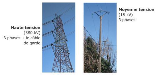
Electricity is transmitted in 3-phase up to the medium voltage network, but residential mains are usually supplied in single phase (between one phase and neutral).
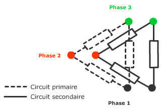
On the medium voltage network (15 kV on the diagram below) a third cable carries the neutral, recreated by the transformer.
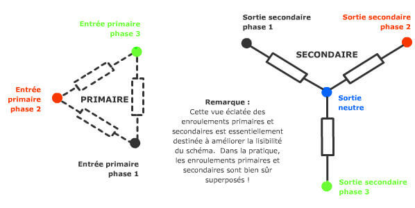
Creation of a neutral potential by the transformer
The primary windings of the transformer are wired in Delta configuration (as we will see later in ‘3-phase transformer’) while the secondary windings are wired in Wye (or Star) configuration; the centre of the “star” is now the neutral.
Why single phase?
We just saw that the loads on the 3 phases of a 3-phase network need to be balanced.
The network operator who resells electricity as single phase to the user can distribute evenly the power in the 3 phases to different users, so that overload problems are avoided, as well as their consequences such as power outages.
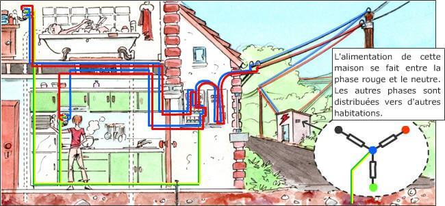
One phase and the neutral are directly connected to our electric meter. They then are routed through the electrical panel and to the various outlets and receptacles as well as the lighting fixtures.
The voltage available at an outlet is the potential difference between both wires: one is connected to one phase of the distribution network, the other to the neutral. Thus we have 230 V between the two wires (120 V in the US). The third wire is the earthing wire.
In our single phase installations, between phase and neutral, the voltage is about 230 V (the standard guarantees between 220 and 240 V). However, the 3-phase low voltage network is at 400 V between phases.
400 V between the low voltage network phases and 230 V between phase and neutral? Absolutely! The voltage between phases is 1,73 (square root of 3) times higher than the voltage between one phase and neutral. Why? Because of the phase shift between the three phases.
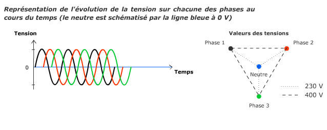
Attention: 230 V and 400 V are effective voltages, not the peak values which are square root of 2 times higher (see the module “Basic electricity”)
Transmission lines do not have a neutral cable, (most of the time), so the only relevant voltage is that between phases (380 kV, 75 kV…).
Earthing
As to earthing an installation, several arrangements are possible: TT, TN (C or S) and IT. These codes indicate the type of neutral connection.
The first letter shows the type of connection used by the power supplier:
- T: direct connection between neutral and earth
- I: isolated, which means no connection between neutral and earth (or high impedance connection).
The second letter shows the type of connection used by the user:
- T: direct connection between the electrical equipment and earth
- N: connection between the electrical equipment and neutral.
In the case of a TN configuration, a third letter is required:
- TN-C: neutral and protective earth (“PE”) are one and the same. In order to differentiate from usual names, this conductor is called PEN for protective earth/neutral
- TN-S: neutral and protective earth are separate.
Each configuration has advantages and disadvantages. The choice will depend on the type of building and on the level of protection required (*).
(*) The choice of a particular earthing arrangement depends on the results of a needs analysis with regard to the essential technical characteristics:
- Safety: in case of fault, this criterion takes into account the risk incurred by people as well as the fire or explosion risk.
Advantage to IT, but TT is a good compromise. TN with its high earth default current should not be used in installations where explosion or fire hazards are present. - Availability: this criterion defines to what extent the power remains available in case of fault.
Advantage to IT… which was designed for that purpose. It is particularly suitable for hospitals where service interruptions are not tolerable. - Maintenance: this criterion considers the ease of troubleshooting in case of fault as well as the simplicity of repairs. Advantage to IT and TT.
- Reliability: how stable is the circuit in case of fault? Advantage to IT and TT.
- Disturbances: this criterion determines to what extent disturbances are generated or propagated by the installation that could affect the powered equipment. Advantage to IT and TT.
Residential electrical installations (or any that is supplied by a low voltage network) in Belgium, France, and the Netherlands use mostly the TT configuration. The TN-C arrangement is primarily used in the USA and British- influenced countries.
A fundamental difference between TT and TN-C configurations is the frequent current in the conduits which will systematically be subjected to parasitic potentials (lower than today’s safety standards, but which cause higher contact currents than TT). TN-C’s attractiveness is its lower cost.
Excerpt from Prof. J.L. Lilien’s course “Effets indirects des champs électromagnétiques” (in French). The complete document may be downloaded from the service de Transport et Distribution de l’Energie Electrique (under “Enseignement”) site at the Université de Liège, where you will also find schematics of the various earthing configurations.
In Belgium and neighbouring countries, the TT configuration is prevalent. Thus the neutral conductor under the responsibility of the power supplier and the local “earth” are separate. The mains cannot be connected to the same earth for this protection. The earth conductor is the protective earth conductor (green and yellow).
The purpose of the earthing system is to drain the leakage current to the ground in order to prevent potentials that could be high enough to be hazardous. Each device (washer frame, electric oven, etc.) must be connected to the protective earth via the green and yellow wire (in Europe). In case of internal fault, the metallic parts of the device (washer frame, etc.) remains at a very low potential compared to the ground, eliminating the danger to someone touching the washer with one hand and the floor with his feet.
The earthing conductor resistance must be as small as possible (less than 30 ohms). The actual connection to the earth can be done by metallic stakes or, for new construction, by a loop below the foundation.
Electric meter
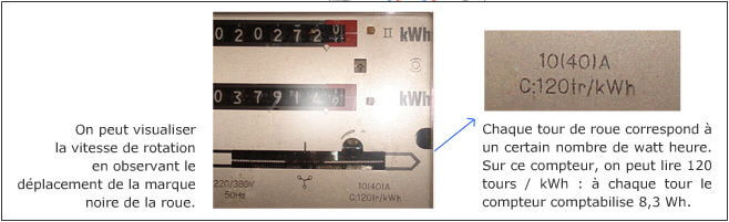
The electric meter (multiple tariff in the example below) is the junction element between our residence and the power distribution network.
It is accompanied by a circuit breaker.
The electric meter is designed to measure the energy consumption over time. It’s a watt-hour meter. The current flowing through the meter windings drives a wheel by magnetic induction. The wheel speed is proportional to the power consumed.
The circuit breaker is a protection device against too intense currents.
When connecting our dwelling to the power network, we request from the supplier a certain amount of power, the maximum demand. It is the maximum power available from the network.
For a maximum demand of 9 kW, the maximum current will be 40 A. If too many appliances are on simultaneously, the main circuit breaker trips in order to prevent overheating of our residential installation, as it is not designed to handle such high currents.
Electrical panel
The electrical panel is the nerve centre of our installation. The various circuits within the residence all start from it. It also contains major protection elements, for both people and equipment, such as circuit breakers, fuses and RCDs.
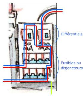
RCDs (residual current devices)
RCDs are designed to detect differences in the forward current (on one phase) and the return current (on the neutral). If the leakage current exceeds a predetermined value (which could be hazardous to people), the RCD will trip. Leakage currents are normally drained via the installation’s earth connector.
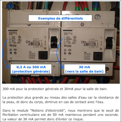
RCDs protect against electrocution hazards by interrupting the faulty circuit faster than serious damage could occur to someone’s body (25 to 40 ms).
Attention:
If we are isolated from the ground (insulating soles or flooring), and we touch both live wires, we will be subject to electrocution, possibly lethal, whilst the RCD will not trip! The RCD trips only when the leakage is to the earth.
Elementary caution should be exercised even when RCDs are correctly included in the installation!
Fuses and circuit breakers
Fuses and circuit breakers are overcurrent wardens. If the load in a circuit exceeds a predetermined limit, they interrupt the faulty circuit.
Their nominal current rating must be suitable for the design power of the circuit (mostly dictated by the conductors cross section). Overloaded circuits are a major cause of fires.
Both the wire cross section and the circuit breaker current rating (*) must match the design power of a circuit. For example, for:
- A lighting circuit, the standard cross section is 1.5 mm² and the circuit breaker current rating is 16 A.
- A circuit serving outlets that could supply heating appliances (such as a coffee maker), the cross section must be at least 2.5 mm² with a circuit breaker current rating of 20 A.
- An electric stove top and other domestic appliances including heaters or motors, the standard requires a cross section of 6 mm² and circuit breakers rated 32 A.
The values are different for fuses:
- Cross section of 1.5 mm² with current rating of 10 A.
- Cross section of 2.5 mm² with current rating of 16 A.
(*) The current rating of a fuse or circuit breaker is the maximum acceptable effective current. The short circuit current is the current that trips the circuit breaker and interrupts the circuit.
Circuits which have a high risk of overloading (for example the kitchen circuit supplying power to an oven, a stove top, a blender, etc.) must be sized to prevent the circuit from carrying currents slightly higher than the nominal rating for an extended period.
Fuses and circuit breakers differ in their operation: fuses melt under overload (*) whereas circuit breakers trip by means of either an electromagnet responding instantly to large surges (short-circuit) or a bimetallic strip (thermal effect) for longer term overcurrent conditions.
(*) Operation of fuses
We saw in “Basic electricity” that a conductor’s resistance is determined by its resistivity, its length and its cross section. This last parameter is the one involved in fuse design, in order to protect against overcurrent.
They consist of a wire of precise cross section. The area of the cross section determines the maximum allowed load:
- In the older designs, the wire melts under overload conditions. The fuse must then be replaced;
- In so-called automatic fuses, which are actually a type of circuit breaker, the increase in temperature under overload conditions actuates a switch that interrupts the circuit. The fuse can be reset later after it cools down.
The size of fuses and of circuit breakers as well as the conductor’s cross section are specified by standards which in Belgium are promulgated by the Règlement Général sur les Installations Electriques (RGIE).
Appendices
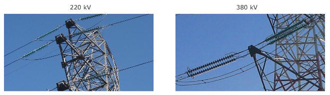
How to recognise the voltage of an overhead high voltage power line?
The isolation between conductors is obtained by the configuration and size of the towers: towers carrying 380 kV lines are much bigger than those carrying only du 75 kV in order to provide the required distance between conductors at 380 kV.
The isolation between conductors and the tower is done by insulators. These are made of glass, ceramic or synthetic material. The higher the voltage the larger the number of insulators. The voltage can thus be estimated by multiplying the number of isolators by 15 kV (more or less depending on the degree of pollution, the insulator shape, etc.). But it gives an idea of voltage of a particular line.
We otherwise know that overhead line voltages are standardised and that there are only a few possibilities. For example, in Belgium, those voltages are: 70 kV (4 to 7 insulators), 150 kV (9 to 11 insulators), 220 kV (13 to 16 insulators), 380 kV (19 to 23 insulators).
If you would like to ask a question regarding a high voltage power line to BBEMG, don’t forget to mention the voltage. This will allow us to respond more precisely.
3-phase transformer
A 3-phase transformer consists of a triple core on which the primary and secondary windings are installed.
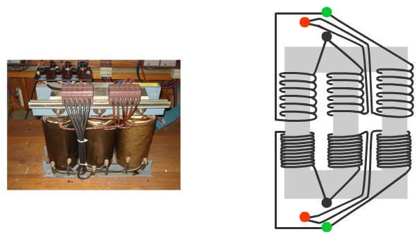
Delta connection
High voltage line transformers are connected in Delta configuration (see figures above and at left).
Documents & Links
- Power network in PDF (667 ko)
- See information in an animated format
(Flash player needed) - http://economie.fgov.be/ (in French or in Dutch)
RGIE (Energie – Electricité – Contrôle des installations électriques)
AREI (Energie – Elektriciteit – Controle van de elektrische installaties)
Topics that might interest you ...
- Electrical concepts – Electrical concepts interesting to have in mind in order to tackle the subject of electromagnetism and electric and magnetic fields without apprehension.
- Electric and magnetic fields – The electric and magnetic fields are distinct concepts that were developed to explain the effects of electricity at a distance. (…)
- Electromagnetism – Electromagnetism is the study of charge interactions at a distance, of currents and electric and magnetic fields. (…)
- Uses of EM properties – How do common domestic electrical appliances work? Based on various examples, we should gain an overall understanding of the operating principle behind those machines that convert electrical energy into thermal or mechanical energy or otherwise make use of electrostatic and electromagnetic properties.