Electromagnetism

Introduction

Electromagnetism is the study of charge interactions at a distance, of currents and electric and magnetic fields. James Clerk Maxwell in 1873 was first to regroup the four fundamental equations which describe the totality of the interactions.

Examples of charge interactions at a distance:

Opposite poles of two magnets attract each other.

Deux aimants dont les pôles opposés se font face s'attirent

Two charges of opposite signs attract each other.

Deux charges de signes opposés s'attirent

Two conductors carrying currents in the same direction attract each other.

Deux conducteurs parcourus par un courant allant dans le même sens s'attirent

Identical poles of two magnets repel each other.

Deux aimants dont les pôles identiques se font face se repoussent

Two charges of the same sign repel each other.

Deux charges de même signe se repoussent

Two conductors carrying currents in the opposite direction repel each other.

Deux conducteurs parcourus par un courant

Strange… Magical…
No! It’s just electromagnetic.
Let’s review all this carefully!

Interactions linked to the electric field

As we saw earlier in “Concept of fields”, charges generate an electric field. What concerns us in electromagnetism is the force exerted by the electric field on other charges present. This force is expressed by the following formula:

Force du champ électrique

It is called Lorentz force. The arrows above F and E denote the fact that they are vector quantities, which means that they have an orientation and a direction.

The force exerted on the charges depends on the charge’s sign: by convention, the force exerted on a positive charge has the same direction as the electric field, while that exerted on a negative charge is in the opposite direction.

Let’s take these two examples:

La force qui s'exerce sur les charges dépend du signe de la charge

In these examples, the electric field is static: its orientation is from + charge to – charge. If the current were alternating, say at 50 Hz, the electric field orientation would change at the same frequency, that is 100 times per second.

In a good conductor, the electric field causes the displacement of the charges. It’s the conduction current: the displacement of the charges is the electric current.

In an insulating material, the electric field creates dipoles by polarising the molecules or reorienting the existing dipoles (*). It leads to the displacement current. The displacement current depends on the capacity of polarisation of the material.

(*) A dipole is a molecule which is positively charged on one side and negatively on the other.

As an example:
A water molecule (H2O) is a dipole since the oxygen atom is negatively charged while the two hydrogen atoms are positively charged.

La molécule d'eau (H2O)

Consequently, the water molecules have tendency to orient themselves in the direction of the electric field. A 50 Hz alternating field will reorient the water molecules 100 times per second.

It is this displacement current which causes food to be heated in a microwave oven; as we saw in “Concept of fields”, the electric field generated is alternating at 2450 MHz, or 1000 million times faster than at 50 Hz.

Conduction and displacement currents are induced by a variable electric field (at 50 Hz here). They flow in both directions alternatively, at the induction field frequency.

Les courants de conduction et de déplacement

Note:

The conduction current exists whether the field is static (until the charges balance the electric field) or variable, whereas the displacement current exists only when the electric field is variable.

Interactions linked to magnetic field

The magnetic force is the manifestation of the magnetic field. It is exerted solely on charges in motion; it is the magnetic component of the Lorentz force. It is expressed by the following formula:

Le champ magnétique est observé via la force magnétique

The force exerted on the charges depends on the charge’s sign, on its velocity, and on the direction of the magnetic field. The arrows above F, v, and B denote the fact that they are vector quantities, with an orientation and a direction.

The direction of the force follow the right hand rule: if a + charge’s displacement is in the thumb’s direction and the direction of the magnetic field is along the index finger, then the middle finger points along the force on a + charge (the reverse for a – charge).

Le sens de la force est donné par la règle des trois doigts de la main droite

Let’s start with a static and uniform magnetic field:

Le champ magnétique du fil de gauche exerce une force sur le fil de droite : c'est la force de Laplace

The left wire magnetic field exerts a force on the right wire: it’s the Laplace force, which depends on the current, the magnetic field and the length of the wire.

Deux fils parcourus par des courants allant dans le même sens ont donc tendance à s'attirer, mais la force exercée est très faible

The right wire magnetic field exerts a force on the left wire as well.

Le champ magnétique du fil de droite exerce également une force sur le fil de gauche

Two wires carrying currents in the same direction will therefore attract each other; but the force is extremely weak.

Note: the magnetic field around the wire is very weak.

In the preceding examples, we were dealing with a static magnetic field. The situation is different when the magnetic field is variable.

Following Ørsted’s observations in 1820 (see “Concept of fields”), Michael Faraday hypothesised that magnetic fields could also produce a current. In 1831, he does actually observe the induction of a current in a circuit, but only with a variable magnetic field (*).

(*) Based on Ørsted’s observations, Faraday thought that any current in a circuit generates a magnetic field which in turn generates a current in a second circuit placed near the first one.

But his first experiments, with direct current, failed to confirm his hypothesis: there was no current in the second circuit.

He noticed however, that when switching the first circuit on and off, a brief current was detected in the second circuit. He then realised that it’s the change in the magnetic field through a given surface, also known as the magnetic flux, which is responsible for the induced currents.

More precisely, the variable magnetic field generates an electromotive force which in turns creates an electric field. It’s this electric field which is producing the current: it is an induced current. It is known as Faraday’s law of induction.

loi de Faraday

Induced currents in turn generate a magnetic field which opposes the changes in magnetic flux that created them. This is Lenz’s law.

When a conductor is placed in a variable magnetic field, an electric field appears in the conductor which in turn generates circular induced currents, called “eddy currents” (or Foucault currents after the scientist credited with discovering them).

courants de Foucault

Experience has shown that magnetic phenomena are influenced by certain materials presence: diamagnetic, paramagnetic, and ferromagnetic materials. They are characterised by their high magnetic permeability, which is their ability to channel magnetic induction: they concentrate the magnetic flux and increase the magnetic induction value.

Conversely, insulating materials such as stone, dry wood, or PVC have no influence on the magnetic field configuration.

Effects on the human body

The human body may be considered a good electrical conductor. In a variable field (for example sinusoidal at a 50 Hz frequency as that produced by the power grid), the body is traversed by a current at the same frequency as that of the ambient field.

Courants induits par CE et CM

The external variable electric field hardly penetrates the body: for an external electric field of a few kV/m, only a few mV/m develops in the body. It mainly causes a charge migration at the body surface. The result is thus a surface current and a residual current through the body.

The external variable magnetic induction field is only lightly disturbed by the body’s presence. Current loops appear in the body that attempt to cancel the external field. In normal conditions of exposure to the 50 Hz magnetic field, these induced currents are well below the natural currents in the body (called “endogenous currents”): for an external field of 0.15 mT, the induced current is about 5000 times smaller than the endogenous currents.

Perception of 50 Hz fields

As we just saw, only very weak currents are induced in the body by an electric field. In general, these currents are not felt as they are not intense enough to excite nerve cells and muscles. The perception threshold varies from individual to individual.

Le seuil de perception des champs 50 Hz est variable d'une personne à l'autre

When the electric field exceeds a 20 kV/m threshold, we perceive a light tingling of the skin and have goose bumps. The phenomenon is called piloerection. It is similar to what happens in the hair-raising experiment in static electricity.

Under certain conditions, we may also indirectly perceive the electric field:

1) Feeling a small electric shock when touching a mass isolated from the ground that is located below high voltage power lines for example: it is due to capacitive coupling.

capacitive coupling

The car below the high voltage power line is subjected to an electric field: it does induce a displacement of charges. The car acquires a certain potential, different than that of the approaching person.

When he touches the metallic surface, the two potentials will even out (*). The electric shock may be unpleasant, but it is not dangerous.
It is this type of phenomenon to which animals drinking at a trough under a high voltage line are subjected. The solution consists of correctly grounding the trough

(*) This phenomenon may look like an electrostatic discharge, but the amount of current and the duration of the discharge are vastly different.

2) Lighting of fluorescent tube

When approaching a fluorescent tube towards the conductors of a high voltage power line, the tube lights up, albeit weakly. Why? The electric field induces a voltage in the tube which excites the gas inside, leading eventually to the emission of light.

Note: The fluorescent tube operating principle is described in the module “Uses of electricity”.

3) Corona discharge noise

Corona discharges are phenomena associated with very strong electric fields. They are manifested as a luminous halo around high voltage overhead power lines under certain conditions (*). These discharges are the cause of sometimes unpleasant noise.

(*) The presence of small protuberances on the surface of conductors, for example a drop of water or snow flakes, or even an insect, cause large increases of the electric field. The corona effect varies drastically in function of the conditions of the external surface and of the atmosphere.

Exposure to a magnetic field similarly induces only very weak currents in the body. At the commonly encountered magnitudes, they are imperceptibles, just like those induced by electric fields.

Only an exposure to much stronger magnetic fields can lead to detectable effects. For example, when subjected to a magnetic field of 10 mT at 50 Hz (that is about 1000 times the maximum seen under a high voltage power line), flashing lights appear in the field of vision. They are called magnetophosphenes. These flashing lights are caused by induced currents at the retina level. These microcurrents disappear as soon as the exposure ends. There is no accumulation of this effect with repeated exposure as is the case with X rays for example.

Under certain conditions, we may also indirectly perceive the magnetic field; particularly notable are interferences from electrical appliances:

Normal operation of an electrical appliance may be disturbed by the electromagnetic field generated by another nearby electrical apparatus. These disturbances are called electromagnetic interference. To avoid difficulties caused by interference, electromagnetic compatibility rules governing electrical equipment must be observed.

Note:

It is important not to confuse biological effects and interferences of an electromagnetic field with some electronic device. Some materials are very sensitive to low frequency magnetic fields. For example, the cathode ray tube computer screen can be perturbed by a magnetic field as low as 1 µT. The interference is due to the refresh rate of the screen display which is close to 50 Hz.

Examples of field properties uses

50 Hz electric and magnetic fields properties are at work as soon as the production starts and during the transmission of electricity. We will explore here the operating principles of alternators and transformers. In “Uses of electricity”, we will talk about their application to common electrical appliances.

Alternator

Power plant alternators convert mechanical energy supplied by water, wind, steam, nuclear fission, etc. into electrical energy. In Belgium, the voltages produced by alternators vary from 10,000 to 20,000 volts.

How is the voltage generated? To illustrate the operation of an alternator, we have installed a winding (the rotor) on an axle between the 2 poles of a permanent magnet (the stator).

Fonctionnement de l'alternateur

The operating principle is relatively simple: it consists of displacing the windings in a magnetic field which will induce an electromotive force. With the above apparatus (the rotor drive in this case is somewhat rudimentary!) the induced electromotive force is 124 mV.

Principe de fonctionnement de l'alternateur: induire des forces électromotrices

(See the Flash animation from the link at the top right)

The rotor consists of a wound coil (actually two windings in series) which, when in rotation, alternatively passes near the north and south poles of the stator. The magnetic field crossed by the coil spires thus varies at the rhythm of the rotation and induces an alternating electromotive force at the corresponding frequency.

In a power plant alternator, the stator is not made of permanent magnets, but of powerful electromagnets. These allow for much higher electromotive forces.

The alternating voltage produced by power plant alternators is at 50 Hz. The frequency is determined by the speed of rotation of the rotor. Moreover, there are 3 independent phases (circuits), as 3 sets of windings are uniformly distributed around the rotor. This means that the induced electromotive forces in each phase are offset, or “phase shifted”; at 50 Hz, this phase shift is 6.7 milliseconds.

Le triphasé est obtenu en triplant les bobines du rotor et en les répartissant uniformément

An alternator produces electrical energy from mechanical energy. We’ll see in “Uses of electricity” that a universal motor simply reverses the operating principle: the electrical energy is converted to mechanical energy (motor shaft rotation).

Transformaters

Transformers are widely used at the power transmission and distribution level as well as in many end use electrical appliances. Their purpose is to either increase or decrease the voltage. We will revisit the utility of both in the module “Power transmission and distribution”.

Here we’ll take a look at the operation of a step-down transformer: the ratio between the primary and secondary voltages is determined by the number of turns in the two windings.

Les transformateurs

(See the Flash animation from the link at the top right)

In the example shown above, there are respectively 40 and 20 turns in the primary winding (green wire) and secondary (white wire). The voltage across the secondary winding is half that of the primary.

The voltage across the secondary winding has the same frequency and the same waveform as that of the primary. The input and output power are also equal (assuming 100% efficiency).

Tension dans le transformateur

Appendices

Magnetic properties of materials

Diamagnetic (silver, copper, water, gold, lead, zinc…), paramagnetic (air, aluminium, magnesium, platinum…) and ferromagnetic (cobalt, iron, mumetal, nickel…) materials are characterised by their magnetic permeability.

In “Concept of fields”, we saw that the relationship between the magnetic field H and the magnetic induction field B is, in a given material, represented by the relation termed “constitutive” : B = µ * H

The magnetic permeability of the material (µ) is the product of the permeability of a vacuum (µ0, expressed in henry/metre) and of the relative permeability (µr, dimensionless):

  • µ0 is a universal constant, 4π . 10-7 H/m
  • µr depends on the material
Les propriétés magnétiques des matériaux

The relative permeability of diamagnetic and paramagnetic materials is very near 1. Their absolute permeability is therefore practically equal to that of a vacuum, or 4π . 10-7 H/m.

Ferromagnetic materials permeability is not constant; it depends on the magnetic field H. For low values of H, the relative permeability can be very high, but it decreases when H increases and can reach 1 beyond a certain threshold because of saturation. For this reason, the relative permeability values below are maximal values (at 20°C) :

Cobalt: 250 / iron: 10,000 / mumetal : 100,000 / nickel : 600

Note: High magnetic permeability materials (mumetal in particular) are potential magnetic shielding materials. Their use however requires extreme caution, lest they lose their effectiveness.

For further information, you may refer to Magnetic field attenuation >>.

Electromagnetic compatibility

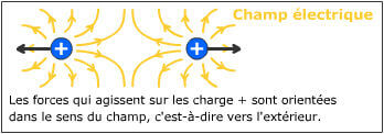
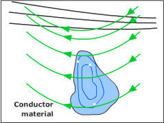
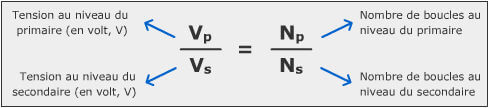
‘Electromagnetic compatibility’ means the ability of equipment to function satisfactorily in its electromagnetic environment without introducing intolerable electromagnetic disturbances to other equipment in that environment. (Source:

DIRECTIVE 2014/30/EU OF THE EUROPEAN PARLIAMENT AND OF THE COUNCIL of 26 February 2014)

To illustrate the concept of electromagnetic compatibility, let’s take the pacemaker example.

A pacemaker (also known as a cardiac stimulator) is a device implanted in a patient’s chest delivering electrical impulses to the heart in order to regulate the beating of the heart in case of malfunction of the natural process.

What happens if a pacemaker is carried into a zone with high intensity fields?

Current pacemakers, in bipolar mode and with a regular ventricular sensitivity (usually 2 mV), the interference risk is practically inexistent with commonly encountered exposures. Pacemakers in unipolar mode or with higher sensitivity are more susceptible to interferences. […] It is recommended not to use small motors (power tools, etc.) in close proximity of the pacemaker casing (Souques, 2004).

As a precaution, in professional environments where intense fields may be present, it is recommended to inquire from the cardiologist what are the type, the programming, and the electromagnetic immunity level of the implanted pacemaker. These precisions will allow the health and safety authority to inform the personnel on the subject.

For more information on the subject, you may refer to the page Workers with pacemaker on the BBEMG website or contact ACE team at Université de Liège.

Reference : Souques, M. (2004). Influence des champs électromagnétiques non ionisants sur les dispositifs cardiaques médicaux implantables. La Presse Médicale, Vol 33, N° 22 – décembre 2004, pp. 1611-1615.

Topics that might interest you ...

  • Electrical concepts – Electrical concepts interesting to have in mind in order to tackle the subject of electromagnetism and electric and magnetic fields without apprehension.
  • Electric and magnetic fields – The electric and magnetic fields are distinct concepts that were developed to explain the effects of electricity at a distance. (…)
  • Uses of EM properties – How do common domestic electrical appliances work? Based on various examples, we should gain an overall understanding of the operating principle behind those machines that convert electrical energy into thermal or mechanical energy or otherwise make use of electrostatic and electromagnetic properties.
  • Electricity network – How does the electrical grid work? All you would like to know about the transmission of electricity from power plant to the outlet on our walls.
Share